SARC Events


SARC Events


FoxHunt
Video
SARC Courses
Course Information
Field Day
Video

2020-05-30

2020 IOTA Expeditioner of the Year Award


Award to SARC Member Mike Zavarukhin VE7ACN

The IOTA (Islands On The Air) Program is an exciting and innovative activity that has caught the interest of thousands of radio amateurs worldwide. Established in 1964, it promotes radio contacts with stations located on islands around the world to enrich the experience of all active on the amateur bands and, to do this, it draws on the widespread mystique surrounding islands. It is administered by Islands On The Air (IOTA) Ltd (called here IOTA Management) in partnership with the Radio Society of Great Britain (RSGB).


Mike (in the grey T-shirt) at SARC-SEPAR Field Day


Mike adding to our Field Day score

Our very own Mike Zavarukhin VE7ACN has been a very active participant in the program and he has received several awards for his participation over the past several years. This year he came in first so...

A big congratulations to SARC member Mike Zavarukhin VE7ACN/RW0CN on receiving the 2020 IOTA Expeditioner of the Year Award! The award was announced live on Ham Nation on May 27, 2020.


Read Mike's SARC profile in our newsletter 'The Communicator
and a description of his Russian station


~ SARC


2020-05-29

Temporary Rule Waivers Announced for 2020 ARRL Field Day


Club scores will be permitted from distributed stations

With one month to go before 2020 ARRL Field Day, June 27 - 28, the ARRL Programs and Services Committee (PSC) has adopted two temporary rule waivers for the event:

1) For Field Day 2020 only, Class D stations may work all other Field Day stations, including other Class D stations, for points. 

Field Day rule 4.6 defines Class D stations as "Home stations," including stations operating from permanent or licensed station locations using commercial power. Class D stations ordinarily may only count contacts made with Class A, B, C, E, and F Field Day stations, but the temporary rule waiver for 2020 allows Class D stations to count contacts with other Class D stations for QSO credit.

2) In addition, for 2020 only, an aggregate club score will be published, which will be the sum of all individual entries indicating a specific club (similar to the aggregate score totals used in ARRL affiliated club competitions).

May/June 2020 Communicator
Ordinarily, club names are only published in the results for Class A and Class F entries, but the temporary rule waiver for 2020 allows participants from any Class to optionally include a single club name with their submitted results following Field Day.

For example, if Podunk Hollow Radio Club members Becky, W1BXY, and Hiram, W1AW, both participate in 2020 Field Day -- Hiram from his Class D home station, and Becky from her Class C mobile station -- both can include the radio club's name when reporting their individual results. The published results listing will include individual scores for Hiram and Becky, plus a combined score for all entries identified as Podunk Hollow Radio Club.

The temporary rule waivers were adopted by the PSC on May 27, 2020.

ARRL Field Day is one of the biggest events on the amateur radio calendar, with over 36,000 participants in 2019, including entries from 3,113 radio clubs and emergency operations centers. In most years, Field Day is also the largest annual demonstration of ham radio, because many radio clubs organize their participation in public places such as parks and schools.

Due to the COVID-19 pandemic, many radio clubs have made decisions to cancel their group participation in ARRL Field Day this year due to public health recommendations and/or requirements, or to significantly modify their participation for safe social distancing practices. The temporary rule waivers allow greater flexibility in recognizing the value of individual and club participation regardless of entry class.

ARRL is contacting logging program developers about the temporary rule waivers so developers can release updated versions of their software prior to Field Day weekend.

Participants are reminded that the preferred method of submitting entries after Field Day is via the web applet. The ARRL Field Day rules include instructions for submitting entries after the event. Entries must be submitted or postmarked by Tuesday, July 28, 2020.

The ARRL Field Day web page includes a series of articles with ideas and advice for adapting participation this year.

~ ARRL


2020-05-24

Antenna Modelling... A Follow-up


VA7NF Helps Explain What is Going On Here… 

In the last post, I described my experience with modeling and construction of a quarter wave 80 m inverted L antenna.  I stated that, while the model reliably predicted the real-life behaviour of the antenna, there were also some puzzling results beyond my understanding with the use of various antenna analyzers,  so I asked Stan VA7NF to apply his technical expertise to interpretation.   Other readers’ comments are also invited. 

Part 1 – Measurements Made at the Antenna

Here is a summary of my questions and Stan’s explanations:
Because the feedpoint of the antenna is at ground level, I was able to make one set of measurements without the feedline present then a second set at the station location with the feedline present.  


An AIM 4170 analyzer was connected to the antenna at the feedpoint by a 1 m long RG8X jumper.  I first adjusted the series capacitor at the feedpoint to bring series reactance (Xs) to zero at 3750 KHz.  Initially, each scan and re-scan produced the SWR curves below, showing a large number of random spikes, with each re-scan producing another set of spikes at different frequencies.  The first scan [below] is in red; the re-scan is in orange.

Could the noisy behaviour be the result of strong signals being pickup up by the antenna and interfering with the reflected wave or electronics of the instrument?  To check for the presence of out-of-band signals, I used the AIM 4170 band sweep function from 0.500 MHz (the low end of the broadcast band) to 5 MHz (above the 80 m band) as shown in the graph on the next page. This illustrates two strong, off-scale signals in the AM band (CKST at 1040 and CFTE at 1410 KHz) plus another unidentified signal at 2.0 MHz.  

As I continued with my measurements, the odd behavior shown in the first graph abruptly ceased and I was unable to reproduce it again.  I believe that the improvement came about after all the connections were thoroughly tightened, but it was also coincidentally about the time the weather changed from a prolonged cold, dry spell to very wet.  From that time on, the curves looked “smoother”.


Stan’s comments: 
Your assumptions above are well founded.  Antenna analyzers will send short bursts of RF into the test device (antenna) while monitoring the strength of the return signal.  For short antennae this will normally only be the reflection of its signal; when longer (80M or 160M or our FD antenna 320m) there will be many other strong signals especially the broadcast stations as you noted.

This is where analyzers differ.  Newer ones have Rx filtering that follow the transmit frequency; older ones take a voltage reading of everything on the antenna.  That means the readings are significantly affected by “stray” signals, making them useless in strong fields anywhere in the spectrum.

Your comment about the “noise” changing appears to be directly related to tightening the connectors.  Those two AM stations will mix with themselves, other lesser strength signals, and noise presenting the peaks you saw.  By making a better connection the diode effect of the poor junction has been removed eliminating the mixing products you saw.  Aside from analyzers, any diode (rusty tower bolts, wire fence supports, etc) will mix these strong stations with noise that becomes several S unit Rx background noise.  Doing the math, the 4 large spikes (3620 -3760) appear to be the sum of (1040 + 1410) mixing with 4 other local broadcast stations; also a 3rd peak exists at 2450 being 1040 + 1410.
Incidentally, our 80M antenna at the OTC is producing such images and should also be investigated.

Once the noisy data quietened down, and again scanning with the AIM 4170, the graph [below] showed an SWR close to 1.0, reactance near 0 and R not far off 50 Ω at 3750 KHz.  It doesn’t ever get much better than this, but could I believe it?  I decided to check with another instrument.

Measurements were again made at the antenna, but now using the AA-600 analyzer – results were somewhat different.

As seen in the graphs below, the minimum SWR was now higher at 1.5 but also shifted lower in frequency from 3750 KHz.  Note that at 3750 KHz, the reactance was still showing zero but Rs was around 80 Ω, thereby accounting for the higher SWR.   These results were more in line with my expectations but why did two high-quality instruments show such different results?


Stan’s Comments:
A major part of your low SWR is by design; you have tuned out Xs by adjusting the series capacitor; at 3750 your Xs went from -ve to +ve (tuned resonance) and the Rx value at that frequency as reported by the AIM was 50 ohms.  The RigExpert agrees with AIM that Xs crosses over at 3750 but it says Rs is around 80 ohms and drops as the frequency drops.  The >50 ohm Rx and -ve Xs combine below 3750 for the lower SWR.  It is unknown why there a difference in Rs from 50 to 80 ohms.

Conclusion:  Because they develop different Rs values the SWR curves are different.  By observation there is significant noise still on the wire and that may be the basis of the differences.

Continuing at the antenna, measurements were now made with an MFJ 269 analyzer. 

At 3750 MHz regardless of frequency, the SWR was off-scale (∞) consistent with an unchanging Rs=0 and, in addition, Xs varying erratically, i.e. it was not possible to get a meaningful measurement (note it was confirmed that the analyzer returned appropriate readings when tested with a 50 ohm dummy load and at 20 m on the author’s beam, so the meter seemed to be “working”).   Was this possibly another strong-AM signal interference problem?

Stan’s Comments: 
Agree.  Too much broadband noise for this meter to function.  Not usable on a real antenna with a long length of copper.

Part 2—Measurements Made at Station

Next, a length of new LMR-400 coax plus a short jumper were attached to the feed point along with a second common mode choke close to the station end, but otherwise conditions were unchanged from earlier.  All the following measurements were made at the station end of the transmission line and jumper.


The AIM 4170 produced SWR, Rs and Xs curves across the band. [left]  Zero reactance occurred now at a higher frequency than previously, and instead of rising into positive (inductive reactance) territory at frequencies above 3750 MHz, Xs decreased, showing a net capacitive reactance. How can this be explained?

Stan’s Comments:
Coaxial cable when connected to a matching impedance (50 ohms) will not affect the apparent impedance regardless of length;  however:
1) When connected to a non-matching impedance there will be returning currents with a +/- Xs.
2) As the current flows back it will be a “normal” sine wave changing phase until at 1 wavelength it again matches the phase of the forward wave.
3) RF on a coax cable does not travel the same speed as RF in free space.  Specifications show this as a velocity factor (VF) which is .85 for LMR-400; this means the RF will cycle its phase over less length (1/VF wavelength).  As the test frequency changes this means that the length for a full sine wave will vary being longer at 3.5 MHz and shorter at 4.0 MHz.  Viewing it from a single point (like the feed point) the phase of the reflected signal will vary with frequency.

Putting this together, a reflected signal starting at the antenna connection will be out-of-phase with the forward signal (The +/- Xs as you measured at the antenna).  As that reflected signal moves down the cable its relationship to the forward signal will change, starting at (for example) a +ve phase that will shift to in-phase, then -ve phase, to in-phase, then back to the +ve.

Depending how long your cable is (in wavelengths times VF) the reflected signal will appear + or - phase (Xs) and at places exactly in phase with the signal going the other way.  This combination is what your analyzer will see.  In your image the transformer effect of the length of LMR-400 modifies what is seen.

Another effect of coax transformer effect will be, when the antenna has a high SWR, artificial dips in APPARENT SWR appear; these artificial SWR dips appear when the forward signal is cancelled out by the reverse signal with a resulting Xs=0.  This cancellation effect is frequency dependent so a long coax may show several artificial dips typically 5-10Mhz apart.

Accepted practice is to have feed lines that are ½ wavelength (after applying the VF) but only when attempting to measure at-antenna SWR.  They will NOT appear if the antenna is low SWR as there is no reflected signal to mix with the transmitted one.  This will not eliminate the artificial dips as the length will not be a ½ wavelength across all those frequencies.  This also explains why an antenna that will not tune, may tune if a short length of coax is added between  tuner/transmitter and the antenna.
Continuing with measurements at the station end of the transmission line using the RigExpert AA-600, both the SWR and Rs-Xs graphs now agreed fairly closely with the results for the AIM 4170. [below]


Next using the MFJ 269, the behaviour was once again erratic, with no minimum SWR discernable at any frequency and no meaningful SWR measurable.

I took one further step when I noted that with the AIM 4170 instrument, conditions at the antenna can be measured from the far end of the feedline, if its length, velocity factor and matched loss are known.   As per the Times Microwave specs for LMR-400 giving a velocity factor of 0.84 and matched loss of 0.1 dB/100 ft. (at 1 MHz),  the total length of the cable was known to be 112 ft.  Under these conditions, a “refer to antenna” set of curves measured from the transmitter end of the coax looked like the following.  It was reassuring to note that these curves were virtually identical to those obtained when the measurements were made right at the antenna. 


Stan’s Comments:
The AIM is calculating the coax length effect and applying it to the reflected signal.  Smart!

Conclusions:

On the assumption that strong signals in the AM band (not sufficiently filtered out by the instrument) were the cause of anomalous results, the MFJ 269 readings were rendered useless.

The AIM 4170 analyzer appeared to be influenced by the strong off-band signals, but considerably less so than the MFJ.  

Only the RigExpert AA-600 appeared to be immune to the strong AM signals, and give relatively consistent results at both locations of measurement.

When adjusting for resonance of the antenna/feedline combination, conditions at the station end of the feedline would appear to be the place that counts, as presence of the feedline will influence the resultant impedance seen by the transmitter.  

~ John Brodie VA7XB
  18-02


2020-05-21

Antenna Modelling… A Learning Experience


One of our Tech Topics 

My OCF dipole came down in the wind over a year ago, so I decided it was time to replace it with something else, at least for 80m.  I have lots of trees in the yard, but the high ones really don’t lend themselves to a horizontal wire because they are all clustered together.  I researched other options and decided I could probably make an 80 m inverted L work.   Since my trees are all over 30 m high with the lower branches stripped off, I figured they should accommodate 20 m or more wire in the air, especially since only part of the antenna is vertical.   The relative proportion between vertical and horizontal legs is apparently not too critical to its performance.  This antenna is actually a quarter-wavelength vertical therefore it requires counterpoise, or ground radials. 


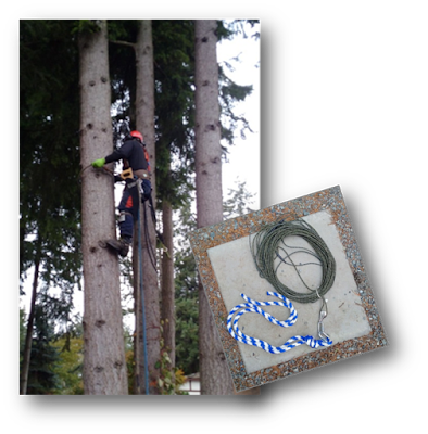
While the weather was good over the summer I began the project by installing a 1½ ” ABS conduit below ground from the house to the location of the antenna feed point, so that the coax would not have to run over the surface of the ground.  Next challenge was to get attachment points up in the trees, a job which requires a tree climber – a big challenge as tree climbers are very casual about returning calls and showing up for the job.  Finally it all came together just as the weather started to turn cold in October.  I had him tie a pulley and rope as high as possible on two trees which are about 10 m apart.  In order that there be no obstruction to the future wire, he had to remove a few limbs but, what the heck, most of them were dead anyway.  The ropes and pulleys went up at about the 20 m level on both trees without a problem.  

I have always wanted to learn about antenna modeling and saw this as an opportunity to get my feet wet.  Several different modeling software packages are available, either free or at low cost, but I elected to use EZNEC demo v 6.0, as it is supposed to do almost everything that the more sophisticated products will do, it has good documentation and is free.  After reviewing the instructions provided with the package, I had no trouble working through the examples to get familiar with its features.  There are also several good tutorials available on You-Tube.   EZNEC does assume that you have a basic understanding of impedance, resistance and reactance which are expressed in the form of complex numbers (Z=R ±jX) as well as familiarity with x-y-z rectangular coordinate systems, but that’s about as complicated as it gets.   I was pleasantly surprised to find out how intuitive the software is to use. 

Taking my guidance from the ARRL Antenna Book, here is the basic configuration that I planned to model: the top portion of the antenna above ground is around ¼ λ long and the other ¼ λ is in the ground in the form of radials or counterpoise.  The bend to make the above-ground wire into an L can be done at any convenient place, but I intended to make most of the antenna vertical. This configuration under normal circumstances will provide a usable swr over most of the 80 m band, with the help of a tuner.  

However, due to the proximity of the wire to ground, its radiation resistance (R) is said to be lower than 50 Ω.  I wanted to aim for 50 Ω at resonance to match the feedline impedance.  If the antenna were to be made somewhat longer than ¼ λ, the R value can be increased to 50 Ω.  However, with the antenna now longer than ¼ λ it becomes inductively reactive.  So I would cancel out the inductive reactance by introducing an equivalent (of opposite sign) series capacitive reactance at the feedpoint – or, as expressed in mathematical form, the impedance would be Z = 50 ±j0 at  resonance.

My objective was to locate the minimum swr at 3.75 MHz, the centre of the 80 m band.  A critical parameter is ground loss but the demo version of EZNEC does not allow modeling of the counterpoise system.  Instead, the ground loss was estimated based on advice in one of the tutorials.  I chose a series load loss of 10 Ω to represent an acceptable but less-than-perfect ground radial system, since I hoped to get by with only 5 radials.  I was soon to find out that 5 isn’t a sufficient number.

After much EZNEC trial-and-error, here is the final antenna configuration:

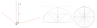
The Far Field elevation and azimuth plots with the maximum gain 25 deg above the horizon, and the antenna is nearly omni-directional, not unexpected for an antenna which is basically a dipole turned on its side.   This antenna will not likely be effective at short range as there is little vertical component to the elevation pattern.

Wire #1 represents a 6’ length of copper pipe to which the counterpoise wires are attached at the bottom; wire #2 is a short horizontal connection from the top of the pipe to the bottom of the vertical wire with the “feedline box” located approximately midway between the two; wire # 3 is the main vertical radiator, and Wire #4 is the short horizontal leg.  The small rectangle shows the location of the coax feed point, and the small circle is ground. 

The total length of the above-ground portion (wires 1-4) is 22.3 m, which is longer than ¼ λ, as intended.  After compensating for the inductive reactance by insertion of a series XC  of -89 Ω in the model, the predicted SWR graph came out as shown below.  At the target frequency of 3750, R was 48 Ω and the reactance virtually zero.

I was also interested in the conditions at the feed point and capacitor.  Since I may want to run at full power, I specified the power as 1500 watts in the EZNEC Options menu.  The result shows that the series reactance-compensating capacitor should have a spacing on the plates that will withstand at least 540 v without arcing when operating within the band. To provide -89 Ω of XC, the capacitance would be about 480 pF based on the formula XC = 1/2πfC.


And now for the construction

Three items were included in the feedline junction box: 
  • a common mode choke, 
  • a 30-1000 pF variable capacitor to introduce series capacitive reactance as described above, and 
  • a surge arrestor, all as shown in the photo.   


Five counterpoise wires, each 22.3 m long and buried 10 cm below the surface of the ground, were soldered to a 6 ft. ½ inch copper pipe driven into the ground and connected at the top to one side of the choke.   The ground wires ran from the base of the copper pipe all around the yard wherever I could fit them in, in all cases with bends to accommodate obstructions and the constraints of the property boundary. Instead of the store-bought choke I could have used a coax coil looped through ferrite toroids, which would have done the same thing.  I put insulation around the ground rod to protect children and animals from RF.


Since the feed point for this antenna is at ground level, it made it possible to conduct measurements right at the antenna without the presence of a feedline.  


Above, the scans  of SWR, R and X were made with the club’s RigExpert AA-600 analyzer. 

You will note that the minimum SWR is about 1.5 and it is also shifted slightly from 3750 kHz.  The higher SWR than predicted is because the impedance is not 50 Ω but 79 Ω – comprised almost entirely of R since the reactance was tuned out (observe the green reactance line crosses the 0 Ω axis at 3750 kHz).

Now this would actually be a very acceptable match across the entire band, but it does indicate that more counterpoise wires would be beneficial in order to match the model.  If we return to the model and simulate a poor ground by increasing the load R from 10 Ω to 30 Ω, the model confirms that the minimum SWR does in fact rise to 1.5.   So I plan to add more ground wires while I monitor the SWR and  impedance (both of which should come down) as the work progresses.  

I was gratified to find that changes made to the physical configuration were consistent with the model’s predictions.  This exercise has given me confidence in the modeling software and a better understanding of how the components of impedance inter-relate with the physical characteristics of the antenna. 

In the next installment I intend to outline a few things that did not make sense, and ask for advice in their interpretation, e.g. 
1) how 3 different analyzers gave me 3 distinctly different results and 
2) how introduction of the feedline also affected the results.


~ John VA7XB
  18/01


2020-05-18

Disaster Preparedness for Amateur Radio


Save yourself! 

In any emergency, before you can even think about contributing your skills as an Amateur Radio Operator, you need to save yourself and your family first. You can’t possibly consider turning on the radio if you haven’t got what you need personally to survive. So in order of importance, you come first, then family, pets and only after those are taken care of can you consider making your way to a radio. If you are well prepared, this process can be very quick, since it will already be completed as part of your emergency plan.

There are a lot of places on the internet that can give you ideas for personal Grab & Go kits and other personal preparedness kits.  I’m not going to try to put together a list of items, for your personal kit, because it’s been done over and over and over. The thing with all those lists is that they all vary in some way. They all vary because everyone has different needs. Some people have medications. Some have pets and quite a few it seems, have guns! Most of the USA kit recommendations that I have seen talk about personal security preparedness as part of the necessities of a kit. I agree completely that personal security can be a consideration for people and it should be part of your thought process. In Canada you’ll just have to replace the words “pointy stick” any time you read the word “gun”. All joking aside though, as you look through some of the results you’ll find when you do a Google search on “Grab and Go” kits or “Preparedness Kits”, you will certainly find things on those lists that don’t seem to apply to you. Don’t discount any of the ideas too quickly. Give them a little thought. You might be surprised at the sense that some of them make. Every persons situation is different and that’s why I’m not itemizing a list for you. Just make sure you are prepared! QSL?!

Now it’s the radio’s turn!

If you plan on making yourself available for Amateur Radio Communications if a disaster strikes then you will need to prepare a few things in addition to the personal preparedness kit you have developed.
Don’t move onto this preparedness list until you and your family are personally prepared.  You can’t help someone else, if your own life is in turmoil. Once you are personally ready then, and only then, do the following:


  1. Train regularly with SEPAR.  While it’s true that presently most of our training has been on the 2 metre Nets, it is still important.  Those of you that never check-in and then believe you will be an asset during a real disaster will surely find yourself in a confusing situation. The adage YOU PLAY LIKE YOU PRACTICE, may be sports oriented, but it applies to much of life. Those of you that have listened to the Nets over the past few weeks have heard a few good situations come up - people checking in and interrupting to get their personal message out, net control having technical troubles and disappearing for a time, and scrambling to amend a simplex frequency when one becomes busy just after it’s announced to be used, and the QSY has already started. 
  2. Don't depend on computers, cellphones, iPads and the internet to store and acquire the informalion you might need in a disaster (Such as the location of City assets- Fire Halls, Recreation Centres). The important stuff should be on paper.
  3. Use paper to do Net Control and not computer software like Excel. If you prefer the computer normally then use paper on occasion to make it easier to switch to paper when it is needed.
  4. While the City of Surrey provides us with Grab & Go Kits, It wouldn’t hurt to have your own Amateur Radio G&G Kit to supplement your personal G&G Kit. Amateur Radio works well in disasters because so many operators have their own equipment. There is excellent redundancy in the system.  Some items to include:


  • Portable radio, antenna and power supply or batteries.
  • If you use HF then you’ll need (or highly recommended) a headset or earphones (Also useful in case you are in a noisy are)
  • Cables and Extension cords.
  • Pencils and Paper (Net Control sheets are handy to have)
  • Clipboard (Once in the field, there is no guarantee you’ll have a counter to work on.)
  • Radiogram forms (not required, but easier than writing on a blank page)
  • Instructions that you feel you might need such as the list of ARRL numbered radiograms and your list of City of Surrey buildings (Rec Centres and Fire Halls.)
  • Small tools (multi-tip screwdriver, multitools, etc.)
  • EMBC (Emergency Management BC Card).
  • If you have a SEPAR Vest then keep it with your radio G&G kit.
  • Important phone numbers and frequencies. (There is a list of assigned frequencies on separs.net)
  • A Surrey map. Remember Google maps needs a cellar connection.  A paper is a good backup.
  • Flashlight
  • A way to stay dry in wet weather. We have no shortage of rain in Metro Vancouver (Ponchos are very small to store, and cheap to buy.).

5. Let SEPAR know what you are good at. Not everyone will be needed on a radio. Some of you are antenna specialists. Others are good at fixing minor radio issues in a pinch or organizing a group? What are you good at? Some people are better at one job than another person. Volunteer that information.
6. Depending on the situation the help you are needed to give could change. 

For instance:

  • If you don’t need to evacuate your home; Can you deploy at a shelter or EOC for a few hours? Operate from home?
  • If you must evacuate. Can you deploy from where you have evacuated to, such as a shelter?

7. Somethings that you could add to your Radio G&G kit, that should also be in your personal G&G kit, are the following items:

  • Bottled water plus something to eat no like an energy bar.
  • Medications.
  • A small first aid kit. Just a couple bandages couple make a big difference in your comfort if you accidentally cut yourself.
  • Toilet paper - small packets from MRE kits are very handy and don't take up much room.
  • Moist towelettes (a quick way to clean your hands).

This list is just a few suggestions to get you thinking about what you might need. It’s certainly not an exhaustive list but it should give you some ideas of where to start.


~ Roger VA7VH


2020-05-10

Near Vertical Incident Skywave (NVIS) Antennas


HF emergency communications or otherwise, contact stations within the skip zone.

A previous post details Robert VA7FMR’s experiences with a dipole using Hamsticks and a dual bracket. Here is additional information on them and Near Incident Vertical Skywave (NVIS) antennas using Hamsticks. 

SEPAR and many like organizations may be called upon in an emergency to provide ancillary communications for emergency services or primary communications for those emergency service partners who do not have RF communications systems of their own, ESS, The Red Cross and Salvation Army, to name just a few. It is a given that the first stations will be on the higher bands above 50 MHz. Anyone with a Basic License may operate within that spectrum. This should provide reliable communications with modest antennas within the Lower Mainland—no, not just with a handheld and a rubber duckie. Even if many of the local repeaters fail, we should manage to set up a decent network within a few minutes to hours. But what if reliable communications are required for longer distances, for example  to Kamloops or to Seattle, or beyond? VHF and above may not be able to span that distance without gain antennas, placed high with at least 50 Watts of power. HF will be the ‘goto’ bands. We may not need a 60 foot or higher tower to communicate effectively either—this is where NVIS becomes an important emergency communications antenna, especially in the field.

If you recall the antenna theory that you should have picked up in your Basic course, you know that the orientation (horizontal, vertical or somewhere in between) of an antenna will affect its radiation pattern. Much like bouncing a ball off a wall. The greater the angle, the greater the distance the ball bounces away from you. Throw it straight at the wall and it should come pretty close to you on its way back. The same general idea applies to the NVIS antenna. If we cause the RF wave to travel nearly straight up or at a slight angle, it will reflect off the ionospheric layers and come back close to our point of origin. So, if we want to communicate on HF with stations within about 1,500 Kms, we use an antenna that radiates primarily straight up. A DXer on the other hand prefers to talk to stations far away, with a few hops, the farther the better, so DX antennas radiate at angles primarily horizontally to bounce and skip back off the ionosphere for the greatest distance. 


So, the NVIS antenna is one that provides the majority of its radiation at an extremely high angle. That is to say the major lobe is between 75 and 90 degrees to the earth's surface. This will provide excellent omni-directional communication out to a distance of up to about 1,500 Kms with no skip. The maximum frequencies involved will be as low as 1.8 MHz under very poor conditions to as high as 14 MHz under excellent conditions, with the most usable being between 3.5 MHz (80M) and 7.3 MHz (40M).


To summarize, NVIS works for frequencies lower than the vertical incident critical frequency—the highest frequency for which signals transmitted vertically are reflected back down by the ionosphere.  At or below the critical frequency the ionosphere will reflect an incident signal arriving from any angle, including straight up. Because the critical frequency is low, you must usually operate 40, 80 or 160 meters or possibly 30 meters to use NVIS propagation.

Under most conditions you can easily obtain coverage on one of these bands from zero to 350 miles or more with no skip zones. On 75 meters with 100 W and an antenna 15 feet high, contacts with stations over 1000 miles away with excellent signal reports are not uncommon. 

These are the characteristics we look for in an emergency-ready HF antenna for distances up to about 1,000 miles… No skip, easy set-up and take down and reasonably reliable communications.

When I first started looking at the NVIS antenna for "local", primarily emergency communications, the consensus seemed to be that it was a dipole-type antenna, near 1/8th wave at the operating frequency, above the ground. I purchased a set of HamSticks, mounted as a dipole, for this purpose as I was operating from a vacation area surrounded by high mountains.  NVIS antennas are commonly used by the military, as their needs fit these characteristics. There is an excellent, though technical article at https://region6armymars.org/downloads/NVIS-Antenna-Theory-and-Design.pdf

Every horizontal antenna has an NVIS component in its radiation. Similarly, every horizontal antenna has a component that is most useful for DX. Your decision then is to pick the configuration that either favours or optimizes the properties you want.  Reliable local communication on HF dictates NVIS. How then do we determine what NVIS antenna will best suit our needs?  Let’s examine the parameters that have a significant effect in antenna performance. This is information on how to make it work reasonably well, NOT a graduate degree treatise on the theory of NVIS.


Height above ground

The antenna height above ground seems to be the single most controversial subject in discussion of NVIS antennas. Some say anything below 1/4 wave works. Others say anything below 1/8th wave and yet others say ten to fifteen feet works very well. You will note that there is negligible difference in antenna gain between 1/8 wave and 1/4 wave height. There is however a significant difference in the logistics of placing an antenna at 70 some feet in the air versus 35 feet in the air.

Antenna guru L.B. Cebik (W4RNL), writing about NVIS antenna elevation, explains that the height, in the 1/8 to 1/4 wave length above ground, has very little difference in gain. In fact, if you roll in the next parameter, ground (detailed below), height can easily have much less effect than ground.

The Near Vertical Incident Skywave (NVIS) antenna is a half-wave dipole antenna, configured straight or as an inverted vee, mounted not over 1/8th wave above ground (at the highest operating frequency). While 1/8th wave works reasonably well, better coverage is obtained if the antenna is mounted at about 1/20th wavelength above ground. A second advantage of lowering the antenna to near 1/20th wavelength is a lowering of the background noise level. At a recent ARRL Section Emergency Test, communication on 75 Meters was started with a dipole at approximately 30 feet. They found communication with some of the other participants to be difficult. A second 1/2 wave dipole was built and mounted at 8 feet off of the ground. The background noise level went from S7 to S3 and communications with stations in the twenty-five and over mile range were greatly enhanced. Simply stated, you want as much of your signal going up as possible and ten to fifteen foot height has shown to function very well. It was also found that a network of stations, all using NVIS antennas experienced much stronger local signals.


Ground

Yet another consideration is the "quality" of the ground below your antenna. By this we mean the conductivity of the ground you are operating above. For any given height (1/4th wave length or less) poor conductivity will attenuate up to 3db more of your signal than high conductivity soil. A documented example is the ARES installation in Longmont, CO at the Emergency Operations Center. That antenna is mounted ten feet above a flat roof. The base for the roof is a grounded steel plate. This antenna consistently performs as well or better than any other in the state. The reason is simple; A full sized resonant dipole antenna mounted ten feet above an excellent ground.

A specific example of how well the Longmont EOC antenna works is one Sunday when testing the antenna, a local ham tried his Yaesu FT-817 running on the internal battery pack. As most know, that configuration produces 2.5 watts PEP maximum output. At that power level he received a signal report from NCS in Colorado Springs (90 miles South) of S9+10db, on 75M just before the net started.

Another example of how the conductivity affects your signals comes from Colorado where they regularly use NVIS antennas on 60M to communicate across the Continental Divide. Doing this on a twice weekly basis for several years now they have established a base-line for comparison. The week of 23 September 2004 they had a slow moving rain storm that put down more than one inch of rain, spread almost evenly over about 36 hours. For those that have thirty to fifty inches of rain per year, that would not be much. In Colorado that is one-fifteenth of their total annual precipitation. After the rain, under less than optimal band conditions, signals were UP 6 to 10db!

The chart by L.B. Cebik's (W4RNL) shows that any NVIS, above excellent ground, out performs an antenna above good ground at optimal height! Hmmm, does that imply that we have found the single most important parameter in NVIS?


Ground wire

Yet another approach is to run a "ground" wire at the surface where the antenna is mounted. A good discussion on this is found at an Australian site by Ralph Holland. He did some research on 160M and found that a ground wire at .02 to .06 wave lengths below the driven element produced the best gain. That translates to about 5 to 15 feet at 75M which would be consistent with the heights seen that have  produced the best NVIS performance. Others claim at least a 6db improvement with this same approach.

Experimenters  also notice an improvement if  you "water" the ground just prior to operation. Pour about one gallon of water on the ground around the ground rod or wire. If it seeps in very quickly, go get another gallon. This has made a noticeable improvement in both transmit and receive signals. 


Counterpoises

The high angle radiation of a dipole (or inverted vee) can be enhanced by adding a counterpoise wire below it, about 5% longer than the main radiating element, to act as a reflector. The optimum height for such a counterpoise is about .15 wavelengths below the main radiating element, but when the antenna is too low to allow for that, a counterpoise laid on the ground below the antenna is still effective.

A knife switch at the center point of the counterpoise can be used to effectively eliminate the counterpoise from the antenna system. This technique is useful for using a dipole for NVIS and longer distances, too. A counterpoise is installed at ground level, or as high as the switch can easily be reached, and a dipole is mounted .15 wavelengths above the counterpoise. When the switch is closed, the vertical gain will increase, and the noise levels will drop. When the switch is open, lower angle gain will increase, improving the antenna's performance for non-NVIS use.


Dual Ham-Stick

This is a portable antenna on a 5-foot mast that does well under ARES/RACES operating conditions. One person can put this up and have it operational in under five minutes! A side advantage of this antenna is its comparatively small size. It is only sixteen feet in length, which makes it much more reasonable for temporary installations.


‘HamStick’ antennas may be paired to make a very usable dipole antenna.
Mounting height will affect  the radiation pattern and therefore propagation.
Above, a typical HamStick and adjustable whip and the dual mount that makes it a dipole with directivity
. 

Inverted Vee

A dipole's close cousin, the inverted vee, is another good NVIS antenna which can be even simpler to support. An inverted vee will work almost as well as a dipole suspended from a slightly lower height than the apex of the inverted vee, so long as the apex angle is kept gentle—about 120 degrees or greater. An inverted vee is often easier to erect than a dipole, since it requires only one support above ground level, in the center.

This design has been successful for the author. It was developed by Dr. Jelinek and is in commercial use by the Armed Forces.


How do I select a frequency for NVIS operation?

The selection of a optimum frequency for NVIS operation depends upon many variables. Among the many variables are time of day, time of year, sunspot activity, type of antenna used, atmospheric noise, and atmospheric absorption. To select a frequency to try, one may use recent experience on the air, trial and error (with some sort of coordination scheme agreed upon in advance), propagation prediction software like VOACAP, near real-time propagation charts (available on the Internet) showing current critical frequency, or even just a good educated guess. Whatever the strategy used for frequency selection, it would probably be best to be prepared with some sort of "Plan B" involving communicating through alternate channels, or following some pre-arranged scheme for trying all available frequency choices in a scheduled pattern of some sort.

http://webclass.org/k5ijb/antennas/NVIS-low-antenna-regional-communications.pdf


A NVIS antenna on a wartime military vehicle.

Finally, this is also an antenna that should be in the ‘kit’ for Field Day or contests. We usually concentrate on working any and all stations however, skip actually works against us when it eliminates many potential contacts up to 1,000 miles or so. The ability to switch to an NVIS antenna will bring in those stations within the skip zone and enhance the score. This strategy has helped us place first in Canada in our 3A Field Day category for several years.

~17/10


2020-05-07

Back to Basics: What is dBi?


Decibels often make our students' eyes glaze over...

The question:

B-006-009-010 The gain of an antenna, especially on VHF and above, is quoted in dBi. The "i" in this expression stands for:

   A. isotropic
   B. ideal
   C. Ionosphere
   D. interpolated

There are a couple of questions in the Basic Question Bank that relate to decibels and to antenna gain measurements. This specific question involves two concepts, measurement in decibels and isotropic antennas.

The decibel (symbol: dB) is a logarithmic unit used to express the ratio of one value of a physical property to another, and may used to express a change in value (e.g., +1 dB or -1 dB) or an absolute value. In the latter case, it expresses the ratio of a value to a reference value; when used in this way, the decibel symbol should be appended with a suffix that indicates the reference value or some other property. For example, if the reference value is 1 volt, then the suffix is "dBV" (i.e., "20 dBV"), and if the reference value is one milliwatt, then the suffix is "dBm" (i.e., "20 dBm"). For Basic exam purposes, it is important to know that +3dB is a doubling and –3dB a halving of a value. For example, question B-006-009-011 asks about the front-to-back ratio of a beam antenna.

The definition of the decibel is based on the measurement of power in telephony of the early 20th century in the Bell System in the United States. One decibel is one tenth (deci-) of one bel, named in honor of Alexander Graham Bell; however, the bel is seldom used. Today, the decibel is used for a wide variety of measurements in science and engineering, most prominently in acoustics, electronics, and control theory. In electronics, the gains of amplifiers, antennas, attenuation of signals, and signal-to-noise ratios are often expressed in decibels.

An isotropic radiator [pictured on the left] does not exist, it is a theoretical point source of electromagnetic or sound waves which radiates the same intensity of radiation in all directions. It is a point in space. It has no preferred direction of radiation. It radiates uniformly in all directions over a sphere centered on the source. Isotropic radiators are used as reference radiators with which other sources are compared, for example in determining the gain of antennas. 

In electromagnetics, an antenna's power gain or simply ‘gain’ is a key performance number which combines the antenna's directivity and electrical efficiency. In a transmitting antenna, the gain describes how well the antenna converts input power into radio waves headed in a specified direction. In a receiving antenna, the gain describes how well the antenna converts radio waves arriving from a specified direction into electrical power. When no direction is specified, "gain" is understood to refer to the peak value of the gain, the gain in the direction of the antenna's main lobe. A plot of the gain as a function of direction is called the radiation pattern.


Antenna gain is usually defined as the ratio of the power produced by the antenna from a far-field source on the antenna's beam axis to the power produced by a hypothetical lossless isotropic antenna, which is equally sensitive to signals from all directions. Usually this ratio is expressed in decibels, and these units are referred to as "decibels-isotropic" (dBi). An alternative definition compares the received power to the power received by a lossless half-wave dipole antenna, in which case the units are written as dBd. 

Directive gain or directivity is a different measure which does not take an antenna's electrical efficiency into account. This term is sometimes more relevant in the case of a receiving antenna where one is concerned mainly with the ability of an antenna to receive signals from one direction while rejecting interfering signals coming from a different direction.

The answer to our initial question therefore is 1. isotropic.

~ John VE7TI
  17/10


CQ CQ CQ

The March - April 2024 SARC Communicator is now available

Another big issue The March - April 2024 Communicator, digital periodical of Surrey Amateur Radio Communications is now available for  viewi...

The Most Viewed...