SARC Events


SARC Events


FoxHunt
Video
SARC Courses
Course Information
Field Day
Video
Showing posts with label Contesting. Show all posts

2024-12-31

The SARC Communicator - January-February 2025

Even better for 2025

New desktop publishing software opens up even more possibilities for the SARC Communicator, the digital periodical of Surrey Amateur Radio Communications. This issue is now available for viewing or download. Another new feature is a smaller version, best suited for mobile devices, available here for viewing or download. The advantage of the larger version being higher resolution graphics and photos. 

The best new feature, in my opinion, is the ability to provide you with a compete Table of Contents [below]. This should enable better accessibility from search engines. 

You will find some great articles in this issue, along with our regular columnists.

Now read in over 165 countries, we bring you 120+ pages of Amateur Radio content from the Southwest corner of Canada and elsewhere. With less fluff and ads than other Amateur Radio publications, you will find Amateur Radio related articles, projects, profiles, news, tips and how-to's for all levels of the hobby.


Download the January - February Communicator in 
LARGE or SMALL format, or read it on-line like a magazine

Previous Communicator issues:

Search for past Communicator issues

and a full searchable index is HERE.  

As always, thank you to our contributors, and your feedback is always welcome. 

The deadline for the next edition is February 15th.

If you have news or events from your club or photos, stories, projects or other items of interest from BC or elsewhere, please contact us at communicator@ve7sar.net

73,

John VE7TI
'The Communicator' Editor


The Table of Contents for the January-February 2025 Communicator issue:

  • The Rest of the Story: Charles Wheatstone 4
  • News You Can’t Lose: Field Day results are in 12
  • Page13—News You Can Lose 13
  • Radio Ramblings: Reflections 15
  • Does  the  Ghost  of  Salvador  Dali  Haunt  ChatGPT? 26
  • Tech: A transceiver on your Android phone 27
  • Xiegu G90 Review 28
  • Another Tape Measure Antenna 31
  • POTA is Calling - Will you answer? 32
  • A Different Kind of Foxhunt 34
  • USA Radio Orienteering Championship 35
  • Mastering iCOM HF: A deep dive into filtering capabilities 37
  • Schooling ChatGPT on Antenna Misconceptions 42
  • LIDS: The Less Involved Data Society 43
  • Experimental Maritime Mobile on 630m 44
  • From the ATV Journal 48
  • B.C. QSO Party 50
  • A Light Dipole 52
  • An Easy Field Strength Meter 53
  • AMSAT - OSCAR 7 55
  • Dutch Amateur Radio Operators Detect Signals From Voyager 1 56
  • Update on the Local High Altitude Balloon Project 57
  • They Don’t Make ‘em Like They Used To… 58
  • LingoSat ISS Deployment 59
  • Canadian Amateur Radio Hall of Fame Appointments 2024 60
  • The Santa Barbara 1925 Earthquake 62
  • Ham Radio Outside the Box: Antenna height matters 65
  • What Did Beethoven Do For Ham Radio? 68
  • VE9KK - The World of CW: I am at peace with the RFI gods 69
  • K0NR - 2 Meters:  Handie-Talkie or Walkie-Talkie? 71
  • Which Modes Have You Operated? 73
  • KB6NU’s Ham Radio: Hurricane Helene 74
  • Pico-based SDR runs stand-alone 75
  • Foundations of Amateur Radio: The venerable QSL bureau 76 
  • No-ham Recipe: Oatmeal brown bread 79
  • Back to Basics: Codes & encryption 80
  • Profiles of SARC Members: Jeanne Wilson VA7QD 88
  • CQ WW DX Contest [CW] 92
  • ARRL 10m Contest 94
  • RAC Winter Contest 96
  • SARC News… 97
  • SEPAR Report 103
  • Ham Leftovers... 107
  • QRT: Blog vs PDF? 108


2024-05-30

A video about ARDF (Radio Orienteering)

Whether you call it Amateur Radio Direction Finding (ARDF), Radio Orienteering, Fox or Bunny Hunting

The feature speaker at our May 2024 meeting was Robert Frey WA6EZV. Robert spoke on ARDF - Radio Orienteering - Fox (or Bunny) Hunting. Robert was first licensed in 1968, and his interests include DX  and ARDF, as an on-foot foxhunter, for over 20 yrs. He was member of the US ARDF National Team in 2000, 02, 04, and 06 competing in China, Bulgaria, the Czech Republic and South Korea.

The presentation was recorded via Zoom so please excuse the video quality which is less than our usual presentations.

Robert Frey WA6EZV

We have documented some of our own SARC  Foxhunts in years past, including this locally developed 80m fox receiver:


and


~ John VE7TI


2024-05-27

Special Event Station TM80DDAY

Commemorating the 80th anniversary of
the Allied assault on Normandy beaches

From June 4 to 9, 2024, a number of crew members of the Plusscouts PA3EFR/J and other Radio Scouters will be traveling to Normandy (Omaha Beach) to support the international activities of the commemoration services around 80 years of D-DAY. 

Operators of this call are the operators of the PA3EFR/J-crew, a specialist group of Scouters, members of Scouting Netherlands through the national Fellowship called Plusscouts. In addition, we have invited some distinguished guests to join our team. This crew primarily brings TDOTA and JOTA to Scouting groups that are eager to get involved in the annual global Radio Scouting activities. Additional information on this years crew can be found on the Plusscouts Website. The station is valid for 2 points in the Dutch Radio Scouting Award scheme.

The good news is that we will be hosted again by the D-Day Museum at Omaha Beach. A radio shack in the backyard of the museum will be part of our radio station and associated radio scouting activities.


QSL cards will be sent out after the event. 


Some specific Radio details:

Radio waves (+- QRM)

1.882 MHz LSB

3.682 MHz LSB

7.182 MHz LSB

14.182 MHz USB

21.182 MHz USB

28.482 MHz USB

DMR TalkGroup 907 - JOTA


We join our fellow Amateur Radio Operators in remembering the brave souls who fought for the liberation of Europe. 

Please help to commemorate this historic event by attempting a contact during the period indicated.


~ Sander PD9HIX
   John VE7TI

2023-09-19

Working POTA: A beginner's guide and video


SARC in the park!

We had an interesting workshop on Saturday, September 16, 2023.  'SARC in the Park' was a presentation by Dmitry VA7DVO for our members interested in POTA activations. You will find more about getting started in POTA at their website, and in our free digital magazine 'The Communicator'.

With an easy to build and inexpensive segmented 5-band wire dipole antenna, we made several of the 17m SSB POTA contacts shown in this video, including Switzerland, Italy and with a mobile station in Northern England.

The antenna plan is at: https://bit.ly/SARC23Sep-Oct on page 45.


Dmitry VA7DVO presenting POTA at the OTC

The on-site demonstration took place at Serpentine Fen Wildlife Refuge

Alex VA7PVC, Dmitry VA7DVO , and Leandro VE7LSI at Serpentine Fen

Here is the presentation on video and a look at the activation

https://youtu.be/RTAKs40DHjQ


Do you want to know what else is happening at SARC?

All our events are now available through our 'live' calendar at: https://ve7sar.net/.

~


2023-03-08

ARRL DX (SSB) Contest


Another successful event

I think we made a commendable showing this weekend,  thanks to all.  Statistics below and log attached.

Thanks to all participants and especially the new guys, Doug and Larry, who jumped in got their feet wet.  

The bands were open although a recent solar storm could have had an impact. Most remarkable was 10m which was wide open worldwide on Sunday morning. The best contact of the event was Namibia, V55Y, by John VE7TI, on Sunday afternoon 10m. Also Reunion Island FR8TZ off the SE coast of Africa.  This is a good way to learn your geography!


~ SARC

2022-07-01

The July-August 2022 Communicator Periodical


125+ Pages Of Projects, News, Views and Reviews

'The Communicator' digital periodical of Surrey Amateur Radio Communications is now available for viewing or download at https://bit.ly/SARC22Jul-Aug 

Read in over 145 countries now, we bring you Amateur Radio news from the South West corner of Canada and elsewhere. You will find Amateur Radio related articles, projects, profiles, news, tips and how-to's. 

This month we welcome back Daniel's Workbench with several projects, plus a new columnist 'Amateur Radio Outside the Box' and much more.

You can view or download it as a .PDF file from: https://bit.ly/SARC22Jul-Aug


Previous Communicator issues are at https://ve7sar.blogspot.com/search/label/The%20Communicator

As always, thank you to our contributors, and your feedback is always welcome. 

The deadline for the next edition is August 20th.

If you have news or events from your club or photos, stories, projects or other items of interest from BC or elsewhere, please email them to communicator@ve7sar.net

Gave a great summer and keep visiting our site for regular updates and news: https://ve7sar.blogspot.ca    

73,

John VE7TI

'The Communicator' Editor


2020-10-25

Transceiver Foot Switches: A Better Solution


Enough of the light footswitch moving out of reach!

Foot switches were never a must-have Amateur Radio accessory… that is until I started contesting about 14 years ago. I used a desk mic and the built-in Push-To-Talk (PTT) switch on the mic base. It was fine for general chats. I switched to a headset sometime around 2000 and it did not have a built-in switch so I started examining alternatives.

My first trial was with a pushbutton hand switch.


It was useful but cumbersome and very unergonomic as I always had to have at least one hand on the button. Not a good choice for contesting, even with the paper logging I was using at the time.

Then I recalled my time in the  E-Comm 9-1-1 call centre. Radio Operators there use a foot switch exclusively, leaving both hands open for other tasks.  My first foot switch was a home-made affair. It worked just fine but did not have the right weight or ‘feel’ and moved around on the floor. I  then modified  a foot pedal from my woodworking tools by removing the AC socket and replacing it with a standard ¼-inch phone plug, the norm for PTT input. 


It was much better, had decent weight and a solid PTT contact as long as my foot hit the correct part of the pedal, something that doesn't always happen in the frenzy of a good contest pile-up or an attempt to get that rare DX.

It wasn’t until about 2008 that I noticed that the sustain pedal on my wife’s Roland piano used a ¼-inch phone plug as well. Although I don’t play myself, I found out that these are quite heavy and  was told that it did not normally move around.

I used that pedal for a while but, to avoid the inevitable: “Did you take my pedal again?” I decided to shop for my own. A trip to a couple of local musical instrument stores produced several good candidates. I tried some out… to questioning stares as I didn’t play a piano while doing so, but instead listened for a smooth and solid click and tossed it in the air a bit to judge the weight. I took one home for $25 with an assurance that I could return it if dissatisfied with the product. It turned out to be a Chinese-made item but it worked like a charm with all the right attributes, and it is still in use today.


As it turned out it also has a normal open (NO) and normally closed (NC) selector switch. Apparently this is because some pianos require that option. For Amateur Radio use the switch should be set to normally open (NO) to trigger the PTT when the pedal is depressed otherwise the radio would transmit constantly except when the switch is depressed.

Amazon has pedals starting around $20 and eBay has them starting at about $15. My recommendation is to visit your local music store and to try a few so you can determine if they tend to slide on the floor, if they have a nice solid click and if they are normally open.

~ John VE7TI

18/12


2020-05-30

2020 IOTA Expeditioner of the Year Award


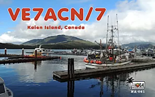
Award to SARC Member Mike Zavarukhin VE7ACN

The IOTA (Islands On The Air) Program is an exciting and innovative activity that has caught the interest of thousands of radio amateurs worldwide. Established in 1964, it promotes radio contacts with stations located on islands around the world to enrich the experience of all active on the amateur bands and, to do this, it draws on the widespread mystique surrounding islands. It is administered by Islands On The Air (IOTA) Ltd (called here IOTA Management) in partnership with the Radio Society of Great Britain (RSGB).


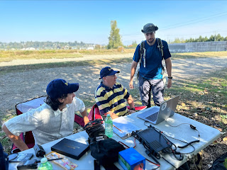
Mike (in the grey T-shirt) at SARC-SEPAR Field Day


Mike adding to our Field Day score

Our very own Mike Zavarukhin VE7ACN has been a very active participant in the program and he has received several awards for his participation over the past several years. This year he came in first so...

A big congratulations to SARC member Mike Zavarukhin VE7ACN/RW0CN on receiving the 2020 IOTA Expeditioner of the Year Award! The award was announced live on Ham Nation on May 27, 2020.


Read Mike's SARC profile in our newsletter 'The Communicator
and a description of his Russian station


~ SARC


2020-05-10

Near Vertical Incident Skywave (NVIS) Antennas


HF emergency communications or otherwise, contact stations within the skip zone.

A previous post details Robert VA7FMR’s experiences with a dipole using Hamsticks and a dual bracket. Here is additional information on them and Near Incident Vertical Skywave (NVIS) antennas using Hamsticks. 

SEPAR and many like organizations may be called upon in an emergency to provide ancillary communications for emergency services or primary communications for those emergency service partners who do not have RF communications systems of their own, ESS, The Red Cross and Salvation Army, to name just a few. It is a given that the first stations will be on the higher bands above 50 MHz. Anyone with a Basic License may operate within that spectrum. This should provide reliable communications with modest antennas within the Lower Mainland—no, not just with a handheld and a rubber duckie. Even if many of the local repeaters fail, we should manage to set up a decent network within a few minutes to hours. But what if reliable communications are required for longer distances, for example  to Kamloops or to Seattle, or beyond? VHF and above may not be able to span that distance without gain antennas, placed high with at least 50 Watts of power. HF will be the ‘goto’ bands. We may not need a 60 foot or higher tower to communicate effectively either—this is where NVIS becomes an important emergency communications antenna, especially in the field.

If you recall the antenna theory that you should have picked up in your Basic course, you know that the orientation (horizontal, vertical or somewhere in between) of an antenna will affect its radiation pattern. Much like bouncing a ball off a wall. The greater the angle, the greater the distance the ball bounces away from you. Throw it straight at the wall and it should come pretty close to you on its way back. The same general idea applies to the NVIS antenna. If we cause the RF wave to travel nearly straight up or at a slight angle, it will reflect off the ionospheric layers and come back close to our point of origin. So, if we want to communicate on HF with stations within about 1,500 Kms, we use an antenna that radiates primarily straight up. A DXer on the other hand prefers to talk to stations far away, with a few hops, the farther the better, so DX antennas radiate at angles primarily horizontally to bounce and skip back off the ionosphere for the greatest distance. 


So, the NVIS antenna is one that provides the majority of its radiation at an extremely high angle. That is to say the major lobe is between 75 and 90 degrees to the earth's surface. This will provide excellent omni-directional communication out to a distance of up to about 1,500 Kms with no skip. The maximum frequencies involved will be as low as 1.8 MHz under very poor conditions to as high as 14 MHz under excellent conditions, with the most usable being between 3.5 MHz (80M) and 7.3 MHz (40M).


To summarize, NVIS works for frequencies lower than the vertical incident critical frequency—the highest frequency for which signals transmitted vertically are reflected back down by the ionosphere.  At or below the critical frequency the ionosphere will reflect an incident signal arriving from any angle, including straight up. Because the critical frequency is low, you must usually operate 40, 80 or 160 meters or possibly 30 meters to use NVIS propagation.

Under most conditions you can easily obtain coverage on one of these bands from zero to 350 miles or more with no skip zones. On 75 meters with 100 W and an antenna 15 feet high, contacts with stations over 1000 miles away with excellent signal reports are not uncommon. 

These are the characteristics we look for in an emergency-ready HF antenna for distances up to about 1,000 miles… No skip, easy set-up and take down and reasonably reliable communications.

When I first started looking at the NVIS antenna for "local", primarily emergency communications, the consensus seemed to be that it was a dipole-type antenna, near 1/8th wave at the operating frequency, above the ground. I purchased a set of HamSticks, mounted as a dipole, for this purpose as I was operating from a vacation area surrounded by high mountains.  NVIS antennas are commonly used by the military, as their needs fit these characteristics. There is an excellent, though technical article at https://region6armymars.org/downloads/NVIS-Antenna-Theory-and-Design.pdf

Every horizontal antenna has an NVIS component in its radiation. Similarly, every horizontal antenna has a component that is most useful for DX. Your decision then is to pick the configuration that either favours or optimizes the properties you want.  Reliable local communication on HF dictates NVIS. How then do we determine what NVIS antenna will best suit our needs?  Let’s examine the parameters that have a significant effect in antenna performance. This is information on how to make it work reasonably well, NOT a graduate degree treatise on the theory of NVIS.


Height above ground

The antenna height above ground seems to be the single most controversial subject in discussion of NVIS antennas. Some say anything below 1/4 wave works. Others say anything below 1/8th wave and yet others say ten to fifteen feet works very well. You will note that there is negligible difference in antenna gain between 1/8 wave and 1/4 wave height. There is however a significant difference in the logistics of placing an antenna at 70 some feet in the air versus 35 feet in the air.

Antenna guru L.B. Cebik (W4RNL), writing about NVIS antenna elevation, explains that the height, in the 1/8 to 1/4 wave length above ground, has very little difference in gain. In fact, if you roll in the next parameter, ground (detailed below), height can easily have much less effect than ground.

The Near Vertical Incident Skywave (NVIS) antenna is a half-wave dipole antenna, configured straight or as an inverted vee, mounted not over 1/8th wave above ground (at the highest operating frequency). While 1/8th wave works reasonably well, better coverage is obtained if the antenna is mounted at about 1/20th wavelength above ground. A second advantage of lowering the antenna to near 1/20th wavelength is a lowering of the background noise level. At a recent ARRL Section Emergency Test, communication on 75 Meters was started with a dipole at approximately 30 feet. They found communication with some of the other participants to be difficult. A second 1/2 wave dipole was built and mounted at 8 feet off of the ground. The background noise level went from S7 to S3 and communications with stations in the twenty-five and over mile range were greatly enhanced. Simply stated, you want as much of your signal going up as possible and ten to fifteen foot height has shown to function very well. It was also found that a network of stations, all using NVIS antennas experienced much stronger local signals.


Ground

Yet another consideration is the "quality" of the ground below your antenna. By this we mean the conductivity of the ground you are operating above. For any given height (1/4th wave length or less) poor conductivity will attenuate up to 3db more of your signal than high conductivity soil. A documented example is the ARES installation in Longmont, CO at the Emergency Operations Center. That antenna is mounted ten feet above a flat roof. The base for the roof is a grounded steel plate. This antenna consistently performs as well or better than any other in the state. The reason is simple; A full sized resonant dipole antenna mounted ten feet above an excellent ground.

A specific example of how well the Longmont EOC antenna works is one Sunday when testing the antenna, a local ham tried his Yaesu FT-817 running on the internal battery pack. As most know, that configuration produces 2.5 watts PEP maximum output. At that power level he received a signal report from NCS in Colorado Springs (90 miles South) of S9+10db, on 75M just before the net started.

Another example of how the conductivity affects your signals comes from Colorado where they regularly use NVIS antennas on 60M to communicate across the Continental Divide. Doing this on a twice weekly basis for several years now they have established a base-line for comparison. The week of 23 September 2004 they had a slow moving rain storm that put down more than one inch of rain, spread almost evenly over about 36 hours. For those that have thirty to fifty inches of rain per year, that would not be much. In Colorado that is one-fifteenth of their total annual precipitation. After the rain, under less than optimal band conditions, signals were UP 6 to 10db!

The chart by L.B. Cebik's (W4RNL) shows that any NVIS, above excellent ground, out performs an antenna above good ground at optimal height! Hmmm, does that imply that we have found the single most important parameter in NVIS?


Ground wire

Yet another approach is to run a "ground" wire at the surface where the antenna is mounted. A good discussion on this is found at an Australian site by Ralph Holland. He did some research on 160M and found that a ground wire at .02 to .06 wave lengths below the driven element produced the best gain. That translates to about 5 to 15 feet at 75M which would be consistent with the heights seen that have  produced the best NVIS performance. Others claim at least a 6db improvement with this same approach.

Experimenters  also notice an improvement if  you "water" the ground just prior to operation. Pour about one gallon of water on the ground around the ground rod or wire. If it seeps in very quickly, go get another gallon. This has made a noticeable improvement in both transmit and receive signals. 


Counterpoises

The high angle radiation of a dipole (or inverted vee) can be enhanced by adding a counterpoise wire below it, about 5% longer than the main radiating element, to act as a reflector. The optimum height for such a counterpoise is about .15 wavelengths below the main radiating element, but when the antenna is too low to allow for that, a counterpoise laid on the ground below the antenna is still effective.

A knife switch at the center point of the counterpoise can be used to effectively eliminate the counterpoise from the antenna system. This technique is useful for using a dipole for NVIS and longer distances, too. A counterpoise is installed at ground level, or as high as the switch can easily be reached, and a dipole is mounted .15 wavelengths above the counterpoise. When the switch is closed, the vertical gain will increase, and the noise levels will drop. When the switch is open, lower angle gain will increase, improving the antenna's performance for non-NVIS use.


Dual Ham-Stick

This is a portable antenna on a 5-foot mast that does well under ARES/RACES operating conditions. One person can put this up and have it operational in under five minutes! A side advantage of this antenna is its comparatively small size. It is only sixteen feet in length, which makes it much more reasonable for temporary installations.


‘HamStick’ antennas may be paired to make a very usable dipole antenna.
Mounting height will affect  the radiation pattern and therefore propagation.
Above, a typical HamStick and adjustable whip and the dual mount that makes it a dipole with directivity
. 

Inverted Vee

A dipole's close cousin, the inverted vee, is another good NVIS antenna which can be even simpler to support. An inverted vee will work almost as well as a dipole suspended from a slightly lower height than the apex of the inverted vee, so long as the apex angle is kept gentle—about 120 degrees or greater. An inverted vee is often easier to erect than a dipole, since it requires only one support above ground level, in the center.

This design has been successful for the author. It was developed by Dr. Jelinek and is in commercial use by the Armed Forces.


How do I select a frequency for NVIS operation?

The selection of a optimum frequency for NVIS operation depends upon many variables. Among the many variables are time of day, time of year, sunspot activity, type of antenna used, atmospheric noise, and atmospheric absorption. To select a frequency to try, one may use recent experience on the air, trial and error (with some sort of coordination scheme agreed upon in advance), propagation prediction software like VOACAP, near real-time propagation charts (available on the Internet) showing current critical frequency, or even just a good educated guess. Whatever the strategy used for frequency selection, it would probably be best to be prepared with some sort of "Plan B" involving communicating through alternate channels, or following some pre-arranged scheme for trying all available frequency choices in a scheduled pattern of some sort.

http://webclass.org/k5ijb/antennas/NVIS-low-antenna-regional-communications.pdf


A NVIS antenna on a wartime military vehicle.

Finally, this is also an antenna that should be in the ‘kit’ for Field Day or contests. We usually concentrate on working any and all stations however, skip actually works against us when it eliminates many potential contacts up to 1,000 miles or so. The ability to switch to an NVIS antenna will bring in those stations within the skip zone and enhance the score. This strategy has helped us place first in Canada in our 3A Field Day category for several years.

~17/10


2020-04-29

More About Antennas, And How To Hide From Apartment Managers


Working the world from my apartment balcony

This type of antenna works well mounted horizontally or vertically, high as a dipole or low as an NVIS antenna for emergency use. -Ed.

Last time, I told you of my costly experiences trying to install an antenna on my 3rd floor apartment balcony. Like many people, I live with antenna restrictions and the management of most complexes have rules regarding what can and can not be placed on the patio. My apartment management is no exception. 

In the previous article, I mentioned the high cost of antennas that claimed super abilities but failed to perform as claimed. I now know, to my cost, that a long wire antenna is about the best you can get but not apartment patio friendly. During one of my recent searches on the Internet for an antenna that would work at my apartment, I found an item about a fellow that was using two reasonably affordable car antennas assembled as a center fed dipole. At the next Saturday morning coffee meeting, I mentioned it to one of the other club members. Low and behold, he mentioned that he had built one using ‘HamStick’ antennas for camping and RV'ing and it performed in a very satisfactory manner. 

When taken apart, which takes only a few minutes, it is very light and very portable. He mentioned that he was not, at the moment, using it. "Would you like to borrow it for a while?" As this was my first opportunity to 'Try before I buy' I jumped at the chance and arrangements were made to pick up the antenna at his earliest convenience. I arrived home at about mid day and was soon out on the patio deck fixing the mount to my portable mast. The mount has two studs instead of the usual one. One stud is the type that grounds itself to the mount and the other faces in the opposite direction and is of the usual coax connector type. The antennas themselves are the MFJ HamStick types, a 48” fiber glass rod wound with the appropriate wire coil for the band you wish to work. They are available for the common Ham bands, and in my case, it was wound for 20 meters. There is a 48” wire whip (sometimes called a 'stinger') that is inserted into the end of the fiber glass rod and is moved in or out to tune the SWR of the frequency you are using. My friend had very conveniently marked the spot to where the two whips should be inserted, which made it very easy for me to get things up and running. I soon realized that a horizontal dipole can be rotated just like a beam antenna, My patio is about 12 feet wide and the assembled antenna is about 16 feet long so only 4 feet of the second whip extends from the end of my patio. My patio faces East so I rotated the antenna to face about South of East.

Since a dipole is Balanced and Coax is Unbalanced, a 1 to 1 Current Balun should be used at the antenna end of the coax or RF will migrate down the Coax braid and could cause painful RF burns to the hands or fingers and create havoc with Computers, TVs and other electronic gear in the room.

I soon had the Coax connected to my radio and I found that the SWR was no more than 1.5 to 1 across the 20 Meter band. With little hope of success, I turned on my radio and started to tune up the 20 Meter band. Suddenly, my speaker loudly announced a CQ call. The caller informed those he hoped were listening that he was located 25 miles North of Cincinnati in the State of Ohio. I answered his CQ call but to my disappointment, he answered another caller. I looked at my power output and found that it was set at only 50 Watts. I hurriedly increased to 100 Watts, to be ready for my next call. Again, to my surprise before I could repeat my call, he said, “I now have VA7FMR” so he had heard me after all, on only 50 Watts. He was not calling in a contest so we had a great chin wag and he was very surprised that I had called on a whip dipole with only 50 Watts. My next contact was a CQer in Hawaii. 

So, for about $150 Canadian you too can have a great dipole Antenna on your Patio that you can rotate as much as your patio permits and no one will notice. I have been using this antenna now for about 2.5 weeks and I have spoken to the apartment manager and he has not mentioned that he had even noticed the antenna. None of my neighbors have mentioned it, nor have they made any complaints. Since you already have the mount and other gear, all you need to change bands is another two stick antennas for say 40 or 80 , meters and it would only take a few minutes to change bands. I have an antenna tuner so I thought that I would try 10 meters and it worked like a charm. I then tried the antenna tuner on the 40 meter band, again with great success. When you are tuning the antenna, tune it for the lowest SWR on the center frequency of the band you are working. That should give you a decent SWR all across the band.

In another article I wrote regarding the purchase of equipment and the need for caution when selecting suppliers, you may remember the digital interface that I purchased because it sounded so good on the manufacturers web page and after it was purchased found it impossible to set up because of the lack of information from the manufacturer. His after sale service was equally bad since he provides none and would hang up the telephone if you asked a question about something not covered in his so called manual. I must admit that parts of the above problems were because of my inexperience and lack of knowledge of the setup procedures of software such as MMTTY, N1MM+ and FLDIGI. There are dozens of settings in each of these pieces of software and since they are used together, if you make a mistake in one of them, the whole fandangle does not work. My experience setting up a SignaLink sound card has given me hope that I may yet get that $275 boat anchor working. I have had success using it for CAT control and a degree of success with CW. My next adventure will be integrating MMTTY with FLDIGY and getting digital to work on it. The most difficult part of my entry into the World of Amateur Radio has not been with the radio equipment that I use, it has been the computer software that actually controls the radio and the sound card and the integration of the three, computer, Radio and sound card. Of course, without an antenna, nothing would work. If there is one piece of advise that a greenhorn like myself could pass on to you, it is, “Never give up” I have spent literally days on the internet and gleaned tons of information that has allowed me to improve my knowledge and understanding of many things in this great Hobby of ours. I hope you learn to enjoy it as much as I do!

~Robert VA7FMR   


2020-04-08

“Get on the Air on World Amateur Radio Day” Special Event: Saturday, April 18


On Saturday, April 18, 2020 (1200Z to 2359Z), Radio Amateurs of Canada is organizing a special on-air event to celebrate World Amateur Radio Day.

https://www.rac.ca/get-on-the-air-on-world-amateur-radio-day-event/


Every year on April 18, Radio Amateurs worldwide take to the airwaves in celebration of Amateur Radio and to commemorate the formation of the International Amateur Radio Union (IARU) on April 18, 1925.

World Amateur Radio Day is the day when IARU Member-Societies can show our capabilities to the public and promote global friendship among Amateurs worldwide.

The theme of World Amateur Radio Day (WARD) is “Celebrating Amateur Radio’s contribution to Society” and this is especially relevant given the important role Amateur Radio will play as the current global crisis unfolds.

IARU President Tim Ellam, VE6SH, provided the following message:

“As I write this the world is in the midst of battling the COVID-19 crisis. A few short weeks ago many of us could not imagine the levels of isolation that we are now dealing with and the sacrifices of many on the frontlines of the pandemic. As we have done in past challenges to our society, Amateur Radio will play a key part in keeping people connected and assisting those who need support.

Having come off my own 14-day isolation after returning from an overseas trip, I am touched by the kindness of strangers who assisted me when I was unable to leave my house. It strikes me Amateur Radio operators, who give so much during these times of crisis, are not limited to assisting over the air. Amateurs are true volunteers and I would encourage everyone to assist in the community as they are able to.

My wish for this World Amateur Radio Day is for everyone to stay safe, follow the advice of medical professionals and use Amateur Radio and your skills to help us through this crisis.”


Radio Amateurs of Canada has decided to hold a new “Get on the Air on World Amateur Radio Day” special event in which we encourage as many Amateurs as possible to get on the air and contact as many RAC stations as possible.
  • RAC official stations will operate across Canada from 1200Z to 2359Z on April 18. The RAC official station call signs are VA2RAC, VA3RAC, VE1RAC, VE4RAC, VE5RAC, VE6RAC, VE7RAC, VE8RAC, VE9RAC, VO1RAC, VO2RAC, VY0RAC, VY1RAC and VY2RAC.
  • Those contacting one or more of these stations will be eligible for a special commemorative certificate noting their participation in RAC’s Get on the Air on World Amateur Radio Day Event.

Note: Starting at 1800Z, VA3RAC will be active in the Ontario QSO Party and will be sending the contest exchange. Stations contacting VA3RAC after 1800Z are encouraged to send their contest exchange in return (state/province/country or Ontario county).

For more information on World Amateur Radio Day and the special event please visit:

https://www.rac.ca/operating/world-amateur-radio-day-april-18/

Glenn MacDonell, VE3XRA
President, Radio Amateurs of Canada


Alan Griffin
RAC MarCom Director


www.rac.ca
720 Belfast Road, #217
Ottawa, ON K1G 0Z5
613-244-4367, 1- 877-273-8304
raccomms@gmail.com

Update April 9, 2020: 

The use of the VE7RAC call sign is available via application to myself (forwarded to the RAC Regulatory Affairs Officer). Multiple stations can use the call provided there is only one station on each band/mode slot at any time. I will co-ordinate this. Logs are to be sent to dir.bc.yukon@rac.ca and/or regulatory@rac.ca.

This is an opportunity for people to get on the air, celebrate World Amateur Radio Day and get a pretty PDF certificate using whatever their band/mode is.


~ 73 Keith VE7KW


2020-03-12

Fox Hunting


Also known as Amateur Radio Direction Finding (ARDF)


Another Great Meeting Presentation


Amateur radio direction finding (ARDF, also known as radio orienteering, radio fox hunting and radiosport) is an amateur radio sport that combines radio direction finding with the map and compass skills of orienteering. It is a timed race in which individual competitors use a topographic map, a magnetic compass and radio direction finding apparatus to navigate through diverse wooded terrain while searching for radio transmitters. The rules of the sport and international competitions are organized by the International Amateur Radio Union. The sport has been most popular in Eastern Europe, Russia, and China, where it was often used in the physical education programs in schools.

ARDF events use radio frequencies on either the two-meter or eighty-meter amateur radio bands. These two bands were chosen because of their universal availability to amateur radio licensees in all countries. The radio equipment carried by competitors on a course must be capable of receiving the signal being transmitted by the five transmitters and useful for radio direction finding, including a radio receiver, attenuator, and directional antenna. Most equipment designs integrate all three components into one handheld device. (See Wikipedia and HomingIn for additional details) 


Receiver equipment

No radio license is required. The radio equipment carried on course must be capable of receiving the signal being transmitted by the transmitters and useful for radio direction finding. This includes a radio receiver that can tune in the specific frequency of transmission being used for the event, an attenuator or variable gain control, and a directional antenna. Directional antennas are more sensitive to radio signals arriving from some directions than others.

Most equipment designs integrate all three components into one handheld device. On the two meter band, the most common directional antennas used by competitors are two or three element Yagi antennas made from flexible steel tape. This kind of antenna has a cardioid receiving pattern, which means that it has one peak direction where the received signal will be the strongest, and a null direction, 180° from the peak, in which the received signal will be the weakest. Flexible steel tape enables the antenna elements to flex and not break when encountering vegetation in the forest. 

On the eighty meter band, two common receiver design approaches are to use either a small loop antenna or an even smaller loop antenna wound around a ferrite rod. These antennas have a bidirectional receiving pattern, with two peak directions 180° apart from one another and two null directions 180° apart from one another. The peak directions are 90° offset from the null directions. A small vertical antenna element can be combined with the loop or ferrite rod antenna to change the receiving pattern to a cardioid shape, but the resulting null in the cardioid is not as sensitive as the nulls in the bidirectional receiving pattern. A switch is often used to allow the competitor to select the bidirectional or cardioid patterns at any moment. ARDF receiver equipment is designed to be lightweight and easy to operate while the competitor is in motion as well as rugged enough to withstand use in areas of thick vegetation.

Les Tocko VA7OM has designed a top notch contest grade ARDF 80m receiver that has now gone into production. It is hoped that it will be available for our annual SARC FoxHunt in May. Once sufficient quantities are in stock they will be available for general purchase. Inquiries may be sent to VA7XB@rac.ca.


Les presented a club meeting program on ARDF and the receiver on March 11, 2020, along with his cohorts Amel Krdzalic VA7KBA and Dave Miller VE7HR. He has shared his presentation slides and two videos.


Les' Slides on ARDF (PDF 5Mb) or Les' Demo with Video (PPS 170Mb)


Les' ARDF Video: Fox Placement and Strategy


A video on the use of the receiver


Our 2019 SARC FoxHunt video


Update!

Our next Fox Hunt was scheduled for May 9th, however it was postponed due to the COVID crisis. The new date is Saturday, August 29. Here is the poster:


~ Updated 2020-08-12


CQ CQ CQ

Five-band HF Linked Dipole [updated January 2025]

An improved build This antenna was first described in the November-December 2023 Communicator. After a year of using it, I’ve developed som...

The Most Viewed...