SARC Events


SARC Events


FoxHunt
Video
SARC Courses
Course Information
Field Day
Video

2017-12-10

Better VHF/UHF Performance


A Communicator Reprise: September 2010 (2)

There is more to your radio than just your radio; and just because you can bring up a repeater with a click of your PTT button, doesn’t necessarily mean you will have a full quieting signal sufficient enough to actually get whole words out.  

I hear far too many stations, be it hand held, mobile or base who consistently try to check into a net or have a conversation with poor quality signals or audio issues.

Here are 6 tips to better VHF/UHF Performance
  1. Use the correct coax cable.  You may be losing transmission efficiency if you’re using coax that’s too small for long cable runs.  Here is a rule of thumb: For runs under 20 feet you can get away with RG58 A/U cable.  Avoid using RG-174 for handheld jumpers.  For runs longer than 20 feet, use RG8 or RG213 or better yet, LMR400.  Over 100’ LMR600.  Use the right connectors too.  You can get away with a good quality PL-259 (UHF) connector up for 144 or even 220 Mhz.  But for 440 MHz you need to start using N-Connectors.  Not only for better low loss characteristics, but because the PL-259 does not present a consistent 50-52 ohm impedance above 300 MHz.  Use the best quality you can afford as the quality of the connector will severely affect your performance.
  2. Stop corrosion with lubrication. Your antenna cables and hardware are extremely susceptible to moisture.  Check the ends and lubricate them with marine or silicon grease and use coax seal or splicing tape for wrapping connections.  You can expect a 10-15 year life span out of your stainless steel or anodized aluminum antenna. Far less for uncoated copper or unprotected aluminum.  Scotch 33 or 88 is the best electrical tape over the layer of splicing tape or coax seal for added protection. [see also http://www.nsarc.ca/tech_archive/Articles/PL-259_Weatherproofing_Article.pdf]
  3. Mount your antenna as high as possible. VHF/UHF communications is determined by line of sight, and the higher you mount your antenna, the further your transmission will carry.  Dense trees, lots of metal in and on buildings will diminish your transmit and receive signals.
  4. Get a higher gain antenna! You’re stuck to 5 watts on a hand held with a rubber antenna that offers negative gain (a loss).  ¼ wave antennas are unity gain or NO gain.  Antennas come in 3, 6, 9-10 or higher DB gain.  Even a 3db antenna on a hand held is going to effectively increase your ability to transmit and receive by a factor of 2 (or twice).  6db is twice as good as a 3db antenna.   You can’t use the repeater as a crutch for a poor signal. Bad in, bad out...
  5. Check your antenna mounting location.  If your antenna is mounted within 3 feet of a parallel metal surface, it will “de-tune” your antenna system and your radio will lose efficiency.  If it’s mounted low on a bumper, next to your AM/FM antenna on your car, or you are using the wrong antenna for the installation – e.g. a 5/8th on the mirror mount, where a ½ wave is a better choice.
  6. Don’t yell into your microphone!  This is FM, not SSB or CB… Get your radio tuned properly, use the original mic or at least one with the same input impedance and don’t over deviate by yelling.  If you have a wide band FM radio, and you are trying to work into a narrow band FM repeater, your audio will sound terrible and yelling only makes it worse.  If you are next to each other or a car length away, then fine… 500 mW is good, you annoy fewer people, the rest of the time use adequate power to have a good signal.


2017-12-08

A Call For Your Opinion...


What Direction To Take?


Calling members of SARC and our readers worldwide to participate.  Our hobby has seen changes over the last century, from nothing through significant DIY, to sophisticated computer-radio combinations.   How will our current membership enhance this legacy; how do our current “Elmers” see the future; what changes at the club level will best move this knowledge into the future.

Myself, as with many hams, employment and family building put radio into the background only to come alive as the nest empties.  This 25-year break opened my eyes to the huge differences; when I left transceivers were just coming in and being cautious of interference was between my station and the public.  That has reversed.

Now, about driving that legacy: “What direction should a club take to guide/drive our future?”  Here are a couple of thoughts upon which comments are invited/appreciated.


In BC over half of the population live in Strata aka HOA areas with accompanying by-laws relating to outside structures – Read that as no towers, masts, or dropping wire off your 20th floor balcony.
  • A local, country and world-wide effort to invalidate these big telecom supported by-laws such as FCC 98-273
  • Publicity to educate (propaganda?) that ham radio towers are insurance against natural disasters (e.g. After several disasters Japanese towers are a neighbourhood plus)
  • Ensure remote (internet) operation is part of the planning process and encourage participation
  • “Your suggestions here”
Our executive is heavily HF biased; not by design but that’s the way it worked out.  This means that direction often follows that same bias.
  • Suggestions for direction and legacy building is needed, neigh mandatory, from experienced VHF operators
  • Much public services involve VHF (parades, cycling events, car rallies) yet the local emergency services group has limited involvement.

There is so much more that cannot fit in this column.

We would like to hear from the Amateur community. Comment below, or better yet, PLEASE SEND SUGGESTIONS including what you, or your local club, are or would like to see happen.  Send to president@ve7sar.net and we will publish a summary in an upcoming Communicator.

Have a happy holiday season, 73

Stan Williams VA7NF
SARC President


2017-12-07

The Inverse Square Law Of RF Signal Strength


A Communicator Reprise: September 2010


The Inverse Square Law when referring to RF signal strength can be expressed from both the transmitted signal and the receive signal end in the following ways;

With an identical antenna at both the transmit site and the receiving station, regardless of whether the antenna is an omni-directional or highly directional antenna, if it took 1 watt of Effective Radiated Power to talk to a station 1 mile/kilometre away, then applying the I.S. Law would mean you need 4 watts for 2 miles, 9 watts for 3 miles, 16 watts for 4 miles, 25 watts for 5 miles... 100 watts for 10 miles/kilometres away.  So if you had 1000 watt ERP output to a no-gain antenna, that would only give you 31.625 miles – line of sight communications.  But that does not take into consideration any propagation, reflections, or the fact that the receiver is generally a lot more sensitive to weak signals… This I.S. Law is saying, for a given amount of signal strength to remain the same at each of the distances above, that is what you’d have to increase the ERP [by distance squared] to accomplish this.


At the receive end, you can look at it this way;  For a given [fixed] ERP at the transmit end, let’s say for example, 100 Watts; The strength of the signal at the receive antenna would be ¼ of that at  2 miles distant [25 watts] , 1/9th  of that at 3 miles [11.1 watts], 1/16th [6.25 watts]  at 4 miles, 1/25th at 5 miles [4 watts], 1/100th at 10 miles [1 watt], 1/1000th at 31.625 miles [100 milliwatts]… ad infinitum…


And that doesn’t take into account, atmospheric and reflective/refractive absorption,  and other losses, such as coax cable losses… this is just in AIR!

So with this in mind, three things come to light.
  • The difference between a transceiver with 100 watts output isn’t going to increase the signal strength much more than a 200 watt transceiver and not really that much more for 1000 watts, when you have to consider dollars spent to get the power increase through amplification. Ok 1000 watts and 100 watts will yield a S-unit increase of maybe 10 units… or 10 db over S9… but at what point over S3 [or the noise floor] could you understand the conversation?
  • Antenna gain, even just 3db is enough to almost double the signal strength – at both ends. So you’d be better off spending the money on better gain antennas, than power amplifiers.  Consider antennas with 3, 6, 10, or 20dbd with a 100 watt transceiver.  What is your ERP at each of those decibel gain figures?
  • It’s absolutely amazing that taking into account this Law, we can hear, under ideal conditions, a 5 watt HF signal half way around the world!


2017-11-30

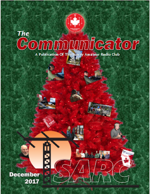
The Communicator - December 2017


Here is the latest Communicator. In this edition you will find:


  • QRM
  • The Rest Of The Story—The Russian Marconi 
  • The Contest Contender 
  • Back To Basics 
  • Radio-Active 
  • What’s Happening This Month In  Local Ham? 
  • News You Can Lose 
  • Club News—SARC 
  • News—OTC 
  • Emergency Comms 
  • Emergency Program News—SEPAR Report 
  • Digital Radio Modes 
  • Amateur Radio News 
  • Tech Topics 
  • Amateur Radio Satellites 
  • RAC News 
  • QRZ
  • and more... 


You can read or download this edition here

My deadline for the January edition is December 18th. If you have news from your Vancouver area club, events or other items of interest please email them to the communicator@ve7sar.net


2017-11-28

Power-Off Time Delay Relay Circuit


A Communicator Reprise: August 2010
For the original article: https://goo.gl/4KZw9z

The two circuits below illustrate opening a relay contact a short time after the ignition or light switch is turned off. The capacitor is charged and the relay is closed when the voltage at the diode anode rises to +12 volts. The common collector or emitter follower has the advantage of one less part, since a resistor is not needed in series with the transistor base. However the voltage across the relay coil will be two diode drops less than the supply voltage, or about 11 volts for a 12.5 volt input.

The common emitter configuration offers the advantage of the full supply voltage across the load for most of the delay time, which makes the relay pull-in and drop-out
voltages less of a concern, but required an extra resistor in series with the transistor base. The common emitter is the better circuit since the series base resistor can be
selected to obtain the desired delay time – I’ve added a variable trim pot for the task to make the delay somewhat adjustable.

The common collector time delay would require changing the capacitor or an additional resistor in parallel with the capacitor to alter the time delay. The time delay for the common emitter will be approximately 3 time constants or 3 x R x C. The capacitor and resistor values can be worked out from the relay coil current and transistor gain. For example, a 120 ohm relay coil will draw 100 mA at 12 volts and assuming the transistor has a gain of 30, the base current will be 100/30 – 3 mA. The voltage across the resistor will be the supply voltage minus two diode drops or 12-1.4 = 10.6 volts. The resistor value will be the voltage/current = 10.6/0.003 = 3533 or about 3.6K ohms. The capacitor value for a 15 second delay will be 15/3R = 1327 µf. You can use a standard 1000 µf capacitor and increase the resistor proportionally to get 15 seconds – thus the convenience of a variable trim pot.

This circuit is handy if your APRS tracker is turned off with your ignition switch. Keeps the tracker on long enough to send its last ‘posit’ before shutting down. In hybrid vehicles, the accessory battery does not drop in voltage quickly [or at all] so a tracker that is waiting for a substantial voltage drop to turn itself off or detect a vehicle at rest, will never sense the required voltage drop in the battery... so a power-off timer is put in line
to make sure the tracker has enough time to send a ‘at rest’ posit and then shut down until the vehicle is started.


2017-11-27

The December Communicator...


On its way December 1st


It’s been a good year for the Surrey Amateur Radio Club. Improvements to the Operations & Training Centre, a Gaming grant and many successful events have raised our profile in both the Amateur and non-Amateur Community. 


We look forward to the year ahead. In the meantime our best wishes for a happy holiday season ahead. The new issue will be posted December 1st.


2017-11-26

Digital Modes Are Gaining Popularity

An Introduction To FT8 Mode


Richard Jannes, PD3RFR

FT8 is a new digital mode, introduced in July 2017 and developed by K9AN (Steven Franke) and KJ1T (Joe Taylor). FT8 stands for "Franke and Taylor, 8-FSK modulate".  It’s similar to JT65, with one big difference. The transmissions duration is only 15 seconds instead of 60 seconds in JT65. This mode was developed especially for contacts where large fluctuations in signal strength occur, QSB for example. A disadvantage is that the sensitivity is 10dB less than JT65. FT8 decodes signals to-20dB.

As in all other digital modes (JT65, PSK31, SSTV etc.) you need to have an audio interface between the transceiver and the computer's sound card. For this I use the MicroHam USB Interface III. Of course you need software that supports this mode, in this case that is WSJT-X version 1.80. This software can also control your transceiver and runs on many versions of Windows (including Windows 10), and is also available for other platforms.

It is very important that your computer clock  is synchronized to the hundredth of a second with the station you are contacting, otherwise you’ll miss a piece of the transfer. For years I’ve used the synchronization of the Meinberg Network Time Protocol. Another option is NetTime, which is easier to get working by a layman.

Here is an example of a QSO as it is intended with FT8, where PA1TEST (fictitious call) responds to my CQ call:

"CQ PD3RFR JO22″ CQ call from PD3RFR (JO22 is the grid square location)
"PD3RFR PA1TEST AB12″ PA1TEST responds to the CQ with its location AB12
"PA1TEST PD3RFR-08″ PD3RFR responds with a signal report
"PD3RFR PA1TEST R-12″ PA1TEST responds (replies) with a signal report
"PA1TEST PD3RFR Rahman" PD3RFR says reception report received
"PD3RFR PA1TEST 73″ PA1TEST says ‘with best regards'
"PA1TEST PD3RFR 73″ PD3RFR says 'with best regards'

Although this passage has lasted only 7x 15 seconds, it seems to be too long for some amateurs. In actual practice, I have regularly seen the following method, in which the actual QSO only takes 60 seconds.

"CQ PD3RFR JO22″ CQ call from PD3RFR (JO22 is the Location)
"PD3RFR PA1TEST-08″ PA1TEST responds with a signal report
"PA1TEST PD3RFR R-12″ PD3RFR responds (replies) with a signal report
"PD3RFR PA1TEST Rahman" PD3RFR says reception report received
"CQ PD3RFR JO22″ PD3RFR goes on to a new general call

It’s handy to use the online PSK Reporter Tool so you can see where your FT8 signal is received with your particular transmitter and antenna setup. Then you don’t need to unnecessarily call stations that you see, but who do not hear you.

On the screenshot of the  WSJT-X program [right] I was in a QSO with an Amateur in Scotland. As with JT65, there is a ‘Waterfall’ display which shows several QSOs. After tuning to an FT8 frequency, you see the received stations every 15 seconds in the ‘Band Activity’ box . If you see an interesting station, click on a CQ message (pink lines) to respond. If you receive an answer, you will see the response in the ‘RX Frequency’ box on the frequency where you send and receive. The colours are set in the software preferences but I just left them at the default. Unlike JT65, the advantage of this software is that it goes through the whole process/QSO by itself. So just click once and the QSO is completed when your contact station responds. If you send out a CQ call, then you can have this answered automatically.

Logging a QSO to an ADIF file is easily done by the program itself. An ADIF file can be opened in settings, or the contact can be imported to another program like HRD Logbook. Of course it’s cumbersome to paste one file into another every time and then also forward it to, for example, LoTW or eQSL. Therefore it’s useful to install an extra piece of software JTAlertX [from version 2.10.1 shown below]. This program allows you to automatically forward an entry to your preferred logbook/application, for example HRD. You can also permit this program to alert you to DXCC and calls that you would like to work in your log.


FT8 is used on different shortwave bands in upper sideband mode. For the novice that is on 10 meters at 28.074 MHz, 20 meters 14.074 MHz, and 40 meters 7.074 MHz.


Because radio amateurs like to unite themselves in clubs, there is a new FT8 Digital Mode Club created through an initiative of two Austrian Amateurs. I’ve joined, you never know what it may be useful for ;-). I received membership number 608, an indication that there are quite a few who have adopted this new mode already.


~ Richard, PD3RFR
   Reprinted with permission
   Translation by Google and VE7TI

For more information and other interesting articles check Richard’s website www.pd3rfr.nl


CQ CQ CQ

The Communicator July - August 2025

A Big One to Last the Summer We're coming up to our club's 50th Anniversary and this is another big issue, with a look back at our h...

The Most Viewed...